


Gear SpecialistBundlingMusician
Call 866‑388‑4445 or chat for exclusive deals, plus save on orders of $199+
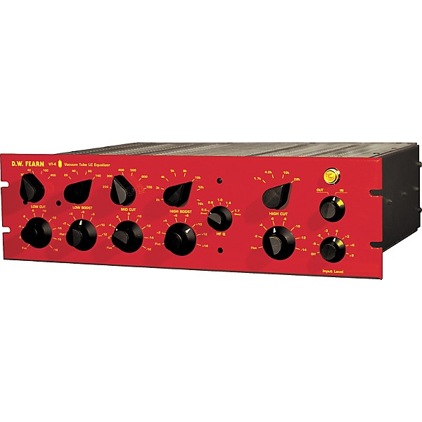
D.W. Fearn VT-4 Equalizer
$6,100.00
D.W. Fearn VT-4 Equalizer
Q&A|Item #:1274319727774
6-month special financing^ + $610 back in Rewards** Limited time Learn More
Order it today! This item is backordered, but you can save your place now so you don’t miss it when it’s back in stock. You won’t be charged until it ships.
Notify me when this item is in stock.
Protect your gearLearn more
Cover drops, spills or cracks with Pro Coverage
Save on orders $199+ and get expert advice from a Gear Adviser
Need Help?

Description


The VT-4 equalizer from D.W. Fearn will change the way you think of EQ. It's smooth and sweet, and can be very subtle at mild settings, but quite strong with aggressive use of the controls. Creative use of the low boost and cut will create a powerful bass that has to be heard to be believed. The high boost adds just the right brightness to vocals, guitars, any sound, or even an entire mix. Even with extreme settings, the VT-4 will never sound harsh.
This single-channel equalizer uses passive LC circuitry with class-A triode vacuum tube stages for the input and output. The tube circuitry is largely derived from the VT-1/VT-2 mic preamp design, so the equalizer has much the same sonic character as the preamps.
The LC-style passive equalization circuitry is based on the classic designs that are still the best-sounding way to achieve high-quality tonal control.
The input is line-level, transformer balanced-bridging. An active vacuum tube input section has adjustable gain to accommodate input signals as low as -10 dBm. The input transformer is made by Jensen. The output stage utilizes the same custom Jensen transformer used on the VT-1/VT-2 mic preamps.
All controls are stepped for precise repeatability and uniform matching between units. High-quality rotary switches are used with 1% metal-film resistors. All of the audio capacitors are polystyrene or polypropylene. The inductors are custom-made by Jensen Transformers Inc.
The D.W. Fearn VT-4 equalizer is constructed of heavy-gauge aluminum, with a 3RU (5.25 inch), 1/4-inch thick front panel, finished in D.W. Fearn red. It matches the VT-1/VT-2 series of mic preamps in appearance and construction.
Like the VT-1/VT-2 preamps, the VT-4 Equalizer has been designed to provide an exceptional tool for audio professionals. The design frequencies and curves were determined by ear, after extensive listening to a variety of program material, both individual tracks and overall mixes. The result is a highly musical EQ with plenty of range for enhancing any track or mix.
Important Note: Due to heat given off by tubes, D.W. Fearn recommends that you provide at least one rack unit (RU) of space above and below their audio rack products. For proper cooling and a refined look for your rack, we highly recommend using D.W. Fearn Vented Rack Panels (#180296).
The History of the VT-4 Equalizer
Throughout my career in recording, there have always been a few equalizers that stood out as being exceptional. Among my favorites are the 1970s-era Neve input-strip EQs, and the Trident CB9066 parametric. I began my equalizer development project by first building a series of test circuits, using all the various tone-modification techniques. After listening to a wide variety of equalization circuits, it was obvious to me that the passive inductor-capacitor (LC) circuit was the one that sounded the most musical and natural to me.
In thinking about how I use equalization, I realized that having simultaneous boost and cut at the low and end frequencies was often very useful. For mid-frequencies, I found that I always cut, usually around 400 Hz, and never had any reason to boost in that range. If I were using a parametric equalizer, I invariably tended to use the low-Q (broadest) settings, and if I had a choice between shelving and peaking on the high and low end, I almost always preferred the shelving curve.
So the VT-4 was designed around those preferences ” low-Q curves, shelving, with simultaneous boost and cut, mid-range cut but not boost, and using passive LC circuitry. The amplification stages would be vacuum tube, and since the VT-1/VT-2 mic preamps have had such a gratifying acceptance in the world of recording, it was important to preserve the same sonic characteristics that distinguished the preamps. I decided to try the Svetlana 6N1P dual triode, and was pleasantly surprised to find that it is a wonderful-sounding tube, with many of the same sonic characteristics as the 6072A used in my preamps. The active tube circuitry fell into place with relatively little effort. Now it was time to make the equalization circuitry work the way I wanted.
To start, I used the filter design tables developed by Bell Labs in the 1930s. That got the project off the ground and it was starting to sound pretty good. For several months, I listened to a variety of music through a prototype equalizer while I was working on other things, and gradually narrowed-in on what sounded really good and what didn't. I would frequently have a box of capacitors and clip leads next to the prototype and often clipped-in a different value here or there and continued listening.
Eventually, the final frequencies, curves, control operation, etc. was determined. To this day, I have only a vague idea of what the actual curves look like. Equalizers, like all audio equipment, should please your ears, not your test equipment. My experience with Jensen Transformers Inc. was so positive that I knew from the beginning that I would utilize their products. The first couple of prototypes used inductors that I wound myself, but for production units, more consistent inductors would be necessary. Jensen agreed to manufacture the necessary inductors to my specifications, and the quality of the parts is astounding
Douglas W. Fearn
Features
- Single-channel equalizer
- Passive LC circuitry with class-A triode vacuum tube stages
- All controls are independent and can be used in any combination
- Input transformer is made by Jensen
- Constructed of heavy-gauge aluminum
Specs
- Performance
- (eq out)
- Frequency response: ±0.2 dB 20 Hz to 20 kHz
- THD: less than 0.06%
- Signal-to-Noise: better than 80 dB
- Low Cut at 30, 40, 100, or 400 Hz, 0 to -18 dB shelving in 2 dB steps
- Low Boost at 20, 40, 60, or 140 Hz, 0 to 16 dB shelving in 2 dB steps
- Mid Cut at 200, 300, 400, 500, 600, or 700 Hz, 0 to -16 dB in 2 dB steps
- High Boost at 1.5, 3, 4, 5, 8, 10, 12, or 16 kHz, 0 to 12 dB in 2 dB steps
- High Bandwidth Q of 0.6, 0.8, 1.0, 1.4, or 1.7
- High Frequency Cut at 1.5, 3.5, 8, or 28 kHz, 0 to -14 dB shelving in 2 dB steps
- Gain adjustable from -9 to +9 dB, referenced to +4 dBm, in 3 dB steps
- (All controls are independent and can be used in any combination)
- NOTE: Frequency is specified in cycles per second (cps) or kilocycles per second (kc). These units correspond to Hz and kHz respectively. Measurements made with -50 dBm input and 50 dB gain in a 22 cps to 22 kc bandwidth. Specifications and price subject to change without notice.
Featured Articles

Be the first to know about exclusive offers, tips and more.


866-498-7882 English
877-687-5402 Español